Introduction
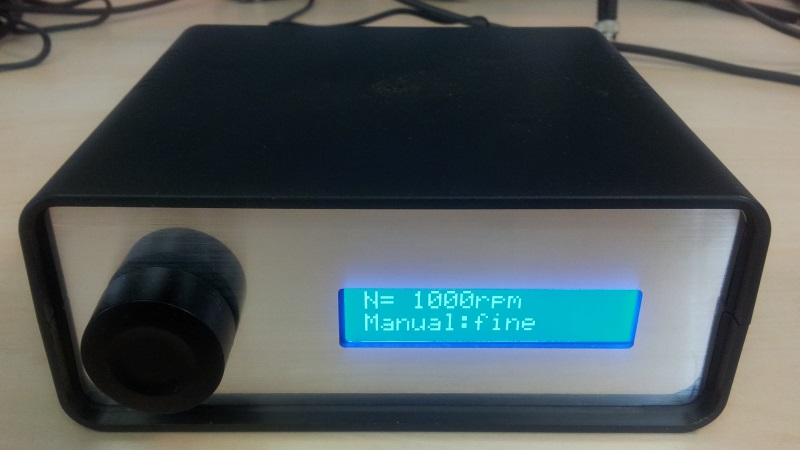
NGen - a low cost, programmable and extendable four channel engine speed
simulator.
Angular signals
In a gasoline or diesel combustion engine, several signals like injection or
ignition have to be created on certain angular positions related to the crankshaft and camshaft
rotation.
For a normal 4-stroke
engine, one complete engine cycle needs two crankshaft rotations which
equals one camshaft rotation.
So every angular position within one engine cycle can be expressed as a
crankshaft angle between 0° and 720°.
To determine the crankshaft position, usually a crankshaft wheel with 60-2
teeth is used where a hall
sensor is utilized to create a rectangular 5V signal that has the same
shape as the unrolled wheel.
 |
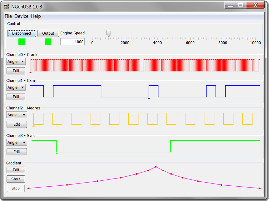
A typical 720° crankshaft signal (red)
with the according camshaft signal (blue):

The two missing teeth define a gap which is used as marker for the
absolute 0° position (e.g. the 1st falling edge after the gap).
Since a full engine cycle has 720°, the position defined by the gap
can be either 0° or 360°.
To distinguish this, the information from a camshaft wheel is used. |
Note how the camshaft is low during the one gap and high during the other. A
simpler camshaft signal with just one 360° low and one 360° high segment
("half moon") would be enough of course to distinguish between 0° and
360°. The depicted multisegment camshaft can be used however to speed
up synchronization and as fallback signal if the crankshaft sensor fails.
Since every engine control unit in a modern car uses the crankshaft and
camshaft information, a simulation of these signals is needed to allow
development of software for automotive applications. Of course there are
commercial simulators available - but these are usually based on Simulink
models running on hardware worth several thousand dollars.
The main idea of NGen is to provide automotive developers with a small and
cheap, yet flexible and extendable simulation box for angular (and other)
signals.
Features
- Autonomous operation via LCD and rotary encoder or remote control
through platform independent (Win/Linux/Mac) Java application that communicates via
USB HID (no drivers needed)
- Engine speed simulation from 0rpm to ±10000rpm in steps of 1rpm
- Angular accuracy of 0.0234375° Crank (6°/256)
- Timing accuracy of 10ns (100MHz clock) with typical ~80ppm clock
accuracy (depends on the crystal)
- Periods down to 1µs supported in time mode and down to 1° Crank in
angular mode
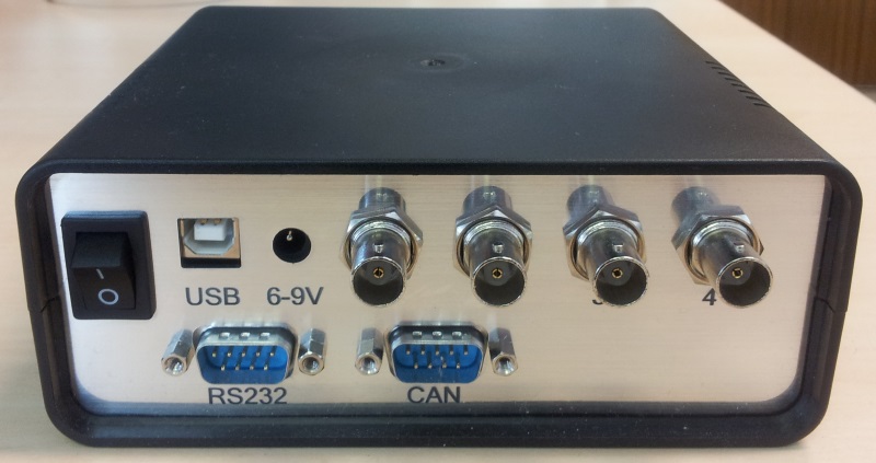
- Four parallel push-pull outputs (5V) with 50Ohm impedance (→ max. 100mA
per output). Short circuit and overvoltage protection
- Each of the four channels can be used in angular mode, time mode or
PWM mode (note: angle or time mode only selectable in groups of
two channels)
- PWM mode allows frequencies up to 100kHz with at least 0.1% DC
resolution (10ns). Frequencies selectable in period steps of 10ns.
- Signal shape in angular or time mode is freely selectable for each
channel (2048 periods per channel)
- Support for bidirectional crank sensors (channel 1 only) with
configurable edges and fwd/rev periods
- Creation of configurable glitches on selected outputs
- Autonomous (no PC needed after setup/start) engine speed gradients
with 1024 points (engine speed and duration), 1kHz update rate, linear
interpolation between points
- 32kByte NVRAM (serial EEPROM) to store signals and gradients
when removing power - automatic restoring of data from NVRAM after power
up
- Device setup (channel data, gradient data etc.) is automatically
downloaded to PC application on connect and can be modified and uploaded
again
- PC software features integrated SENT
signal creation for channels in time mode
- UART and CAN interfaces for future extension e.g. as cheap CAN
interface (not used by software yet)
- Firmware reprogrammable via USB bootloader (virtual file system)
- About 100€ material cost per box (including core board, case,
manufactured PCB and laser cut acrylic front/back panels)
CPU selection
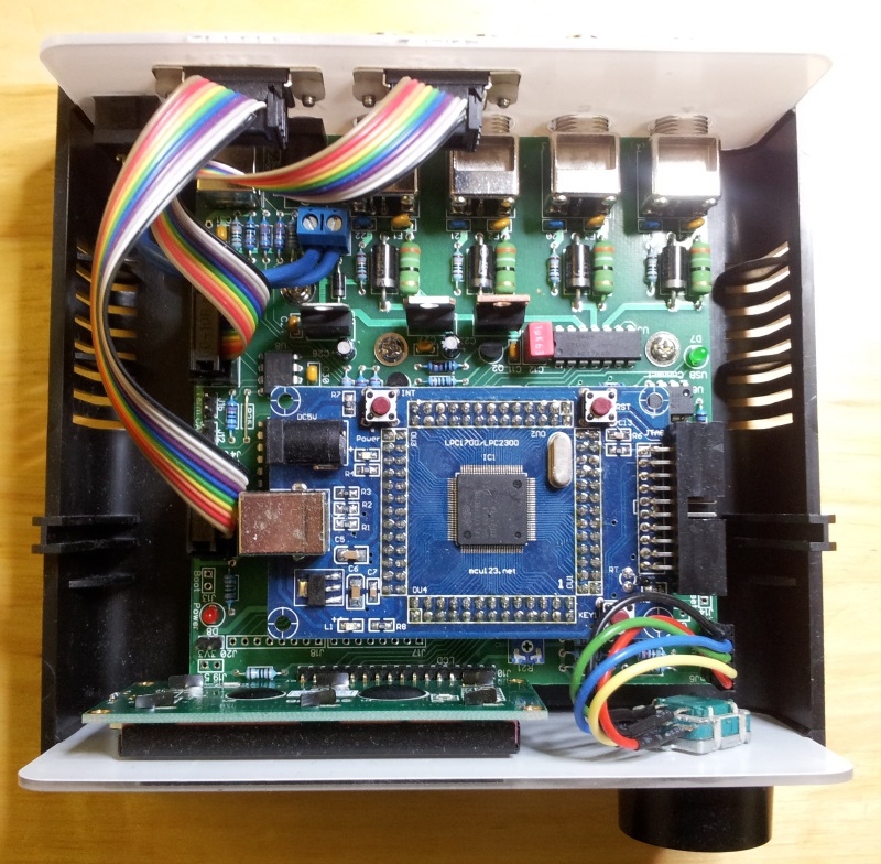
The NXP
LPC1768 was chosen due to its performance and features, but also due
to good availability of demo/core boards.
It's a bit overpowered for this project regarding pin count (100 pin
device) and ROM, but the emphasis was on having an extendable platform and
not on saving a few Euros.
The LPC1768 is a 32bit Cortex-M3 ARM CPU with 100MHz clock (programmable
via PLL), 512kb ROM, 64kb RAM and contains dedicated peripherals for USB,
CAN, I2C, SPI and ADC.
It also features some other interesting peripherals like a quadrature
encoder interface, a 32bit timer peripheral (up to full core clock) with
four timers, fast I/O and a DMA controller.
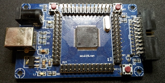
Last but not least, there are core boards available for $20 / 20€
(including postage&packaging) which can be easily integrated into own
projects:
WayEngineer
eBay
Back to main page


